Gyroscopes
A gyroscope’s capacity to stabilise is its angular momentum. This is a measure of how big the rotor is and how fast the rotor is spinning.
Gyro Marine offers gyroscopes from 75,000 Nms to 1,500,000 Nms.
Rated Stabilising Moment is the maximum permissible load realised from the installed angular momentum in normal operation
Gyro Marine offers gyroscopes with stabilising capacities from 200,000 Nm to 1,850,000 Nm.
Location
and Orientation
Gyro Marine gyroscopes can be located anywhere on the ship with equal effect. This includes offset from centreline or offset about center of gravity; vertically or longitudinally.
Installation orientation is with control and electrical connection points oriented towards port and starboard and main accesses oriented forward and aft. This can be so oriented in either of two 180 degree yaw opposed positions.
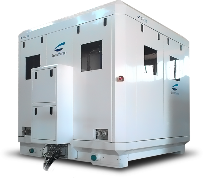
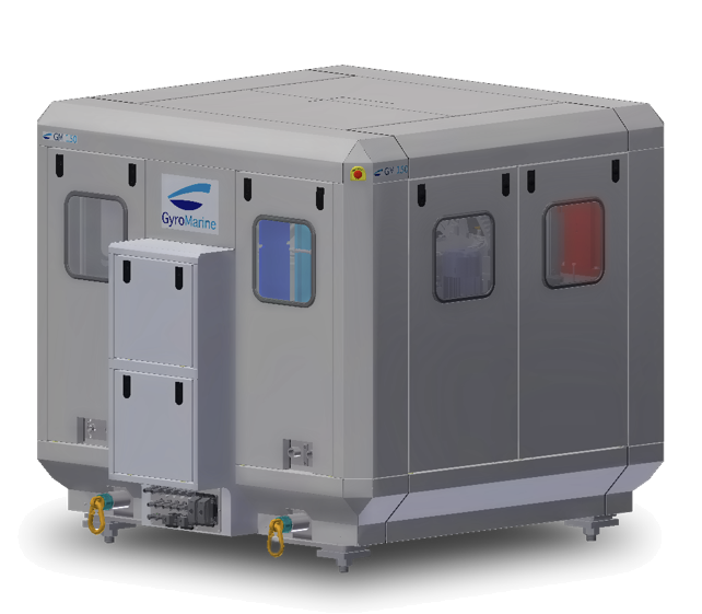
Gyroscopes Range
| GM75 | GM150 | GM300 | GM600* | GM1500 | ||
|---|---|---|---|---|---|---|
| Design Angular Momentum |
kNms | 75 | 150 | 300 | 600 | 1500 |
| Design Stabilising Torque |
kNm | 200 | 350 | 500 | 850 | 1850 |
| Max Angular Momentum | kNms | 104 | 210 | 400 | 720 | 2000 |
| Max Stabilising Torque | kNm | 230 | 400 | 575 | 1000 | 2130 |
| Gyroscope Dimensions (STBD-PORT X FORE-AFT X HEIGHT) | mm | 2340x 1850x H1650 | 2590 x 2170 x H1960 | 2950 x 2470 x H2270 | 3350 x 2710 x H2490 | 4790 x 3590 x H3380 |
| Gyroscope Weight | kg | 6200 | 10000 | 15000 | 23000 | 48000 |
| Electrical Cabinet Dimensions | mm | 1515x 800x H2000 | 2400 x 800 x H2000 | 2400 x 800 x H2000 | 2400 x 800 x H2000 | 3600 x 800 x H2000 |
| Electrical Cabinet Weight | kg | 680 | 1100 | 1200 | 1200 | 2200 |
| Start Up Power Consumption (400 VAC 3Ph+50 Gr 50Hz) | kW | 34 | 56 | 80 | 109 | 202 |
| Steady State Power Consumption | kW | 18 | 25 | 28 | 34 | 51 |
| Seawater Flowrate Demand | l/min | 100 | 135 | 165 | 210 | 390 |
* The GM600 can also be configured in containerised form for temporary deck mounting.
Larger capacity can be met with multiple units. Intermediate capacities can be met by derating a larger unit or with multiple units of different sizes.
A single gyroscope of the appropriate size will always represent the lowest cost and the best weight and volume efficiency compared to multiple smaller gyroscopes. Multiple gyroscopes do, however, provide an additional level of redundancy.
Technical Features

- Simulator
A feature that enables the gyroscope to be utilised to excite the vessel in roll to demonstrate capacity or characterise the ship (or to assist ice clearing in polar explorations)
- Safety
Monitoring of emergency stop and enclosure entry status
In-build load management to limit load applied to ship to design level
Regenerative control in event of power failure to ensure a managed shut down or ride through in case of power interruption
- Service
A dedicated service mode that permits independent operation of sub service circuits and indexing of machine to best orientation for service
In built lift points on all major components.
Self supporting, on machine, attachments points for main tooling for full overhaul in situ
Remote monitoring facility as standard: for connection to ship supplied internet connection
- Motions
Full monitoring and display of ship motions including accelerations.
Internal cross axis algorithms to ensure that gyroscope response is not negatively effected by cross axis motions.
Averaging motions (RMS) displays to show motion trends over time.
- Energy
Monitoring and display of energy consumed by function including energy recovered.
- Active Drive
An all electric drive and brake with internal, fail safe, static brake.
- Rotor
A high strength steel forging precision machined. Fully contained in structural housing with viewing port and internal illumination. Balanced to better than turbine standards for low vibration.
Operating entirely inside a vacuum, with customised high speed vacuum seal technology, to reduce net power consumption. Direct controlled high efficiency, compact electric motor, with regenerative capacity.
- Cooling
Titanium seawater cooler with start/ stop control and monitoring of remote supply pump.
Internal water glycol cooling circuit for all device cooling.
Flow and temperature monitoring on all cooled components including water cooled electrics.
- Lubrication
A sealed oil delivery, scavenge and conditioning system derived from aircraft technology capable of operation in any orientation.
Filters that monitor clogging status and advise when approaching and in need of change.
- Electrical and Network
An active front end offering low voltage harmonics in advance compliance with future classification guidelines of THD <5%.
100 point self monitoring system with advanced warning of any critical condition.
Network fault monitoring.
Cable break and sensor failure monitoring.
- Statistics
Operating history and machine usage logs.
- Ship structural interface
Fully self contained module with single plane mount.
Plugged or field terminable electrical and signal cabling.
- User interface
Ergonomic 12’ or 6” colour touch screen with deep diming capability
User Interface

User Interface
12” and 6” touch screen
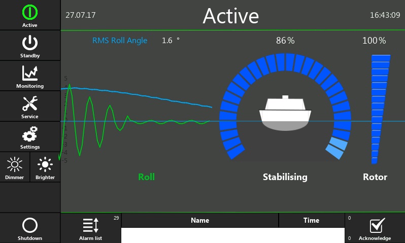
An ergonomic touch screen interface is available in both 12 inch and 6 inch format. Each has identical full featured control and monitoring. Multiple screens are typically used to provide full control from both bridge and local to the gyroscope. Local control should be sited within visual reference of the gyroscope for service. Service mode will be disabled on all other panels.
Normal operation can be realised with single button press Active / Shutdown from any networked user interface.
Each control panel features:
-
- Full colour touch screen
-
- Marine type approved display
-
- UTC clock
-
- Deep dimming on screen
-
- Audible alarm on/off selection
-
- Independent cabinet or console mount
- Ethernet (Cat 6) connection and 24 V DC supply from gyroscope
The control and Monitoring system comprises:
-
- Single button start /shutdown
-
- Standby /active mode change
-
- Alarm messaging with full history
-
- Monitoring:
-
- Motions
-
- Energy
-
- Active drive
-
- Rotor
-
- Cooling
-
- Lubrication
-
- Safety
- Network
-
- Monitoring:
-
- Service mode
- Settings (technician access only)

Ship Interface
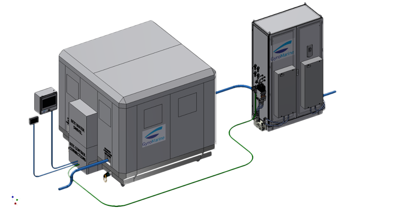
Machine Interfaces to the ship has been simplified to the extent possible to minimise installation complexity and time:
-
- Rigid mount, single plane, 4 point structural interface
-
- Compatible with all hull materials
-
- Three phase AC 380-500V 50/60 Hz factory options
-
- Plugged cable sets
-
- Sea water for cooling (with start request / run monitoring)
-
- NMEA interface
-
- Remote monitoring via Internet
- Ship Monitoring system interface


